

The ultimate destination for players who live and breathe online gaming. Here, every spin, crash, and click tells a story. Whether you’re chasing multipliers in crash games, aiming for precision in plinko and dice, uncovering treasures in online slots, or pursuing life-changing wins in progressive jackpots, Peswiki is your guide through it all.
We explore every genre — from instant-win thrills to strategic slot sessions — revealing the mechanics, volatility, and hidden opportunities behind each title. This isn’t just a database; it’s a player’s encyclopedia built for explorers, strategists, and dreamers alike.
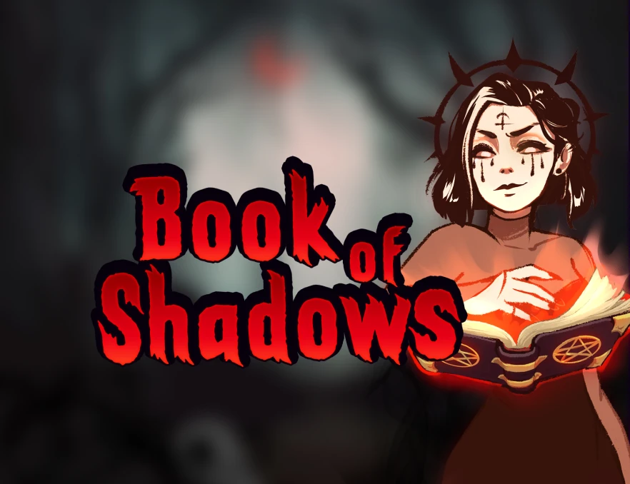
Top slots
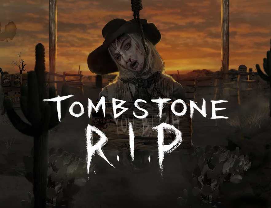
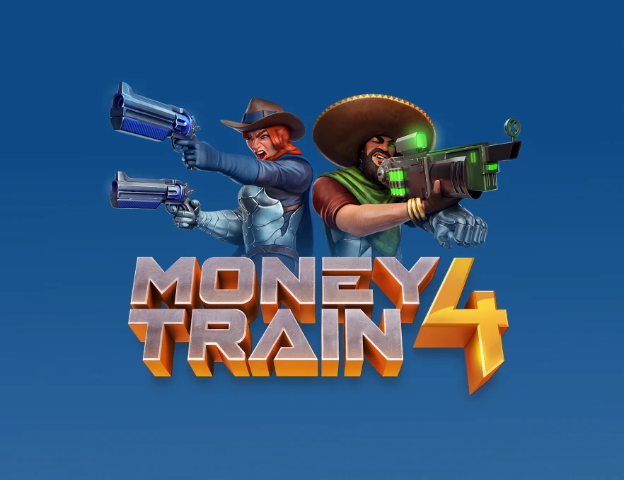
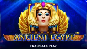
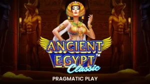
At Peswiki, we break down the slot universe into definitive categories — each appealing to a different kind of player. Best odds slots are defined by high RTP, often above 97 %, like Book of 99 or Jackpot 6000, delivering steady, data-driven value for strategic players. Best payout slots, such as Tombstone RIP or Money Train 4, focus on sheer win potential — sometimes over 100,000× your stake — combining extreme volatility with cinematic gameplay. For the budget-conscious, best low stake slots like Fire Joker and Viking Runecraft start at just €0.05 per spin, offering accessible entertainment with fair RTPs around 96 %.
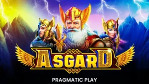
Then come the allrounders, crowd-pleasers such as Sweet Bonanza or Starburst XXXtreme, balancing solid RTPs, moderate volatility, and wide bet ranges from casual to high-roller. Grids vary — from classic 3×3 reels to dynamic Megaways or cluster-pay setups — but the essence remains the same: clear math models, stunning visuals, and diverse risk levels. Comparing providers, Play’n GO excels in balance, Nolimit City dominates volatility, Pragmatic Play blends mass appeal with innovation, and Relax Gaming crafts depth and precision. Whatever your style, Peswiki helps you navigate slots by what matters most — odds, potential, and playability.


Popular slot machines
Check out our slot favorites of the week to find your new best slot!
Choose by vendor


Welcome to Peswiki — Play Every Slot Wiki, if you play for the experience as much as the outcome, Peswiki is where your journey through the world of iGaming truly begins — spin by spin, game by game.
How We Evaluate Games — Turning Data into Insight
At Peswiki, every game is more than just reels and symbols — it’s a data-driven experience. Our team analyses each title through a structured evaluation model powered by ratings and data gathered directly from providers and verified sources. This allows us to measure real gameplay variables — from RTP and volatility to user engagement — and translate them into clear, player-focused insights.
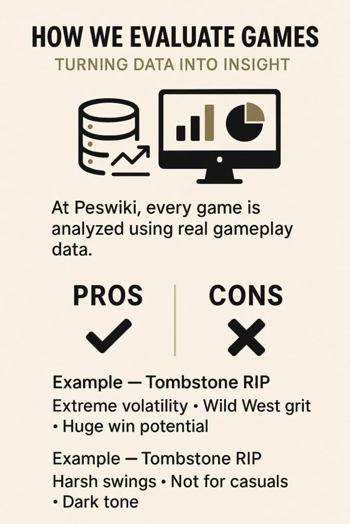
We then break those findings into two short, impactful lists: Pros and Cons. Each statement is short and succinct, making it quick to scan yet meaningful. Pros highlight what excites genre fans — mechanics, atmosphere, or unique features — while Cons reveal what might deter players seeking different gameplay. This dual-view format helps you instantly understand whether a game suits your style or not.
For example, Tombstone RIP might read:
Pros: Extreme volatility thrill | Gritty Wild West theme | Massive win potential
Cons: Not for casual players | Long dry spells | Dark, violent imagery
The result? A concise, unbiased snapshot that helps players make smarter choices, faster — ensuring every spin starts with confidence, not guesswork.